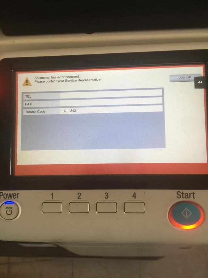
Error codes on Bizhub copiers and how to fix them. Error codes on Bizhub copiers and how to fix them. Like other electronic devices printers, copiers often occur print errors during photo printing. This article I will summarize the error codes on the Bizhub copier as well as how to fix them quickly and effectively. Please.
|
Code |
Describe |
Remedy |
|
C0001 |
LCT Communication Failure |
|
|
C0202 |
Tray 1 Elevator Failure |
1 Check the motor and sensor connections for proper connection, and repair as necessary. 2 Check the connections of each motor for the appropriate drive couplings, and repair as necessary. 3 Check the PU1 connector for proper connection and correct as necessary. 4 PC6 I / O test. 5 PC12 I / O test. 6 PC114-PF I / O test. 7 PC123-PF I / O test. 8 M7 operation check. 9 M8 check operation. 10 M124-PF operation check. 11 M125-PF operation check. 12 Change PWB-A. 13 Change PWB-C2. 14 Change PU1. |
|
C0204 |
Tray 2 Elevator Failure |
1 Check the motor and sensor connections for proper connection, and repair as necessary. 2 Check the connections of each motor for the appropriate drive couplings, and repair as necessary. 3 Check the PU1 connector for proper connection and correct as necessary. 4 PC6 I / O test. 5 PC12 I / O test. 6 PC114-PF I / O test. 7 PC123-PF I / O test. 8 M7 operation check. 9 M8 check operation. 10 M124-PF operation check. 11 M125-PF operation check. 12 Change PWB-A. 13 Change PWB-C2. 14 Change PU1. |
|
C0206 |
Tray 3 Elevator Failure |
1 Check the motor and sensor connections for proper connection, and repair as necessary. 2 Check the connections of each motor for the appropriate drive couplings, and repair as necessary. 3 Check the PU1 connector for proper connection and correct as necessary. 4 PC6 I / O test. 5 PC12 I / O test. 6 PC114-PF I / O test. 7 PC123-PF I / O test. 8 M7 operation check. 9 M8 check operation. 10 M124-PF operation check. 11 M125-PF operation check. 12 Change PWB-A. 13 Change PWB-C2. 14 Change PU1. |
|
C0208 |
Tray 4 Elevator Failure |
1 Check the motor and sensor connections for proper connection, and repair as necessary. 2 Check the connections of each motor for the appropriate drive couplings, and repair as necessary. 3 Check the PU1 connector for proper connection and correct as necessary. 4 PC6 I / O test. 5 PC12 I / O test. 6 PC114-PF I / O test. 7 PC123-PF I / O test. 8 M7 operation check. 9 M8 check operation. 10 M124-PF operation check. 11 M125-PF operation check. 12 Change PWB-A. 13 Change PWB-C2. 14 Change PU1. |
|
C0209 |
LCT Elevator Failure |
|
|
C0211 |
Bypass Lift Motion Failure |
1. Check the SL3 connector for proper connection and correct as necessary. 2 Check cam position .. 3 PC29 I / O check PWB-A. 4 SL3 checking operation. 5 Change PWB-A. |
|
C0212 |
LCT releases Failure |
|
|
C0213 |
LCT Shift Gate Malfunction |
|
|
C0214 |
LCT Switch Failure |
|
|
C0215 |
LCT Shift motor malfunction |
|
|
C0701 |
Manual Paper Size Detection Adjustment Failure |
1. Check the VR1 connector for proper connection and correct as necessary. 2 Adjust VR1 again. 3 Replace VR1. 4 Change PWB-A. |
|
C1080 |
Exit Selection Transfer Failure |
1 OFF Main Switch, wait 10 seconds. or more, and turn ON the Power Switch main. 2 Check PWB-A FN and PWB-A for proper connection, and repair as necessary. 3 Change PWB-A FN. 4 Change PWB-A. |
|
C1183 |
Elevator motor Ascent / Descent drive failure |
|
|
C1190 |
Correction of plate 1 drive failure |
|
|
C1191 |
Calibrate plate 2 drive failures |
|
|
C11A0 |
Paper-Lifter drive failure |
|
|
C11A1 |
Escaping roller pressure / retraction failure |
|
|
C11A2 |
Saddle Exit roller pressure / retraction failure |
|
|
C11A3 |
Shutter drive failure |
|
|
C11A4 |
Saddle Exit Motor Failure |
|
|
C11A5 |
Saddle In & Out Instruction mechanical failure |
|
|
C11A6 |
Saddle Layable Motor Drive Failure Guide |
|
|
C11B0 |
Staple Unit CD drive failure |
|
|
C11B2 |
Staple drive failure |
|
|
C11B5 |
Saddle Staple 1 drive failure |
|
|
C11B6 |
Saddle Staple 2 drive failure |
|
|
C11C0 |
Cam Punch Unit Failure |
|
|
C11D0 |
Wrinkle Motor Drive Failure |
|
|
C2211 |
IU Motor Failure |
1. Check the M2 connector for proper connection and correct as necessary. 2 Check M2 for proper drive coupling, and repair as necessary. 3 Check the PWB-A connector for proper connection and correct as necessary. 4 M2 check the PWB-A operation PJ28A-11 (REM) M-4 5 Change the PWB-A. 6 Change PU1. |
|
C2351 |
Toner suction Fan Motor Fan Failure |
1. Check the M11 connectors for proper connection and correct as necessary. 2 Check for possible fan overload, and repair as needed. 3 Check the PWB-A connector for proper connection and correct as necessary. 4 M11 check the PWB-A operation PJ5A-13 (REM) D-14 5 Change the PWB-A. 6 Change PU1. |
|
C2431 |
IU Fuse Blowing Failure |
1. Check the UN2 connection for proper connection and correct as necessary. 2 Remove the development unit from IU, and then replace UN2. 3 Run F8. 4 Change PWB-A. 5 Change PU1N. |
|
C2557 |
ATDC Sensor Failure |
1. Check the UN2 connection for proper connection and correct as necessary. 2 Remove the development unit from IU, and then replace UN2. 3 Run F8. 4 Change PWB-A. 5 Change PU1N. |
|
C255C |
ATDC Failure Adjustment |
1. Check the UN2 connection for proper connection and correct as necessary. 2 Remove the development unit from IU, and then replace UN2. 3 Run F8. 4 Change PWB-A. 5 Change PU1N. |
|
C2654 |
EEPROM Failure |
1 Disconnect and then connect the power cord. Turn off Main Switch, wait 10 seconds. or more, and turn ON the Power Switch main. 2 Check the EEPROM on the mechanical control board for proper connection, and repair as necessary. 3 Change PWB-A. 4 Change the EEPROM. |
|
C2702 |
Image |
1. Check the settings of Roller Transfer. 2 Change the HV1 |
|
C3451 |
Fusing Warm-Up Failure (Main) |
1 Check if H1 comes on when the main Power Switch is set to ON, and correct or replace as necessary. 2 Check that the aforementioned H2 is when the main Power Switch is set to ON, and correct or replace as necessary. 3 Check the settings of TH1 and TH2, and correct or clean as needed. 4 Check the operation of TH1. Remove CN80 (4P), and then check if the resistances across CN80-2 and -3 on the Thermistor are infinity. 5 Check the operation of the TH2. Remove CN81 (4P), and then check if the resistances across CN81-2 and -3 on the Thermistor are infinity. 6 Check the continuity of H1. Repair or replacement as needed. 7 Check the continuity of H2. Repair or replacement as needed. 8 Change PU1. 9 Change PWB-A. |
|
C3452 |
Fusing Warm-Up Failure (Sub) |
1 Check if H1 comes on when the main Power Switch is set to ON, and correct or replace as necessary. 2 Check that the aforementioned H2 is when the main Power Switch is set to ON, and correct or replace as necessary. 3 Check the settings of TH1 and TH2, and correct or clean as needed. 4 Check the operation of TH1. Remove CN80 (4P), and then check if the resistances across CN80-2 and -3 on the Thermistor are infinity. 5 Check the operation of the TH2. Remove CN81 (4P), and then check if the resistances across CN81-2 and -3 on the Thermistor are infinity. 6 Check the continuity of H1. Repair or replacement as needed. 7 Check the continuity of H2. Repair or replacement as needed. 8 Change PU1. 9 Change PWB-A. |
|
C3751 |
High Temperature Fuser Failure (Main) |
1 Check if H1 comes on when the main Power Switch is set to ON, and correct or replace as necessary. 2 Check that the aforementioned H2 is when the main Power Switch is set to ON, and correct or replace as necessary. 3 Check the settings of TH1 and TH2, and correct or clean as needed. 4 Check the operation of TH1. Remove CN80 (4P), and then check if the resistances across CN80-2 and -3 on the Thermistor are infinity. 5 Check the operation of the TH2. Remove CN81 (4P), and then check if the resistances across CN81-2 and -3 on the Thermistor are infinity. 6 Check the continuity of H1. Repair or replacement as needed. 7 Check the continuity of H2. Repair or replacement as needed. 8 Change PU1. 9 Change PWB-A. |
|
C3752 |
High Temperature Fuser Failure (Sub) |
1 Check if H1 comes on when the main Power Switch is set to ON, and correct or replace as necessary. 2 Check that the aforementioned H2 is when the main Power Switch is set to ON, and correct or replace as necessary. 3 Check the settings of TH1 and TH2, and correct or clean as needed. 4 Check the operation of TH1. Remove CN80 (4P), and then check if the resistances across CN80-2 and -3 on the Thermistor are infinity. 5 Check the operation of the TH2. Remove CN81 (4P), and then check if the resistances across CN81-2 and -3 on the Thermistor are infinity. 6 Check the continuity of H1. Repair or replacement as needed. 7 Check the continuity of H2. Repair or replacement as needed. 8 Change PU1. 9 Change PWB-A. |
|
C3851 |
Low Temperature Fuser Failure (Main) |
1 Check if H1 comes on when the right side door is opened, then close the door, and correct or replace as needed. 2 Check that the aforementioned H2 when right Side door is opened, then closed, and correct or replace as needed. 3 Check the settings of TH1 and TH2, and correct or clean as needed. 4 Check the operation of TH1. Remove CN80 (4P), and then check if the resistances across CN80-2 and -3 on the Thermistor are infinity. 5 Check the operation of the TH2. Remove CN81 (4P), and then check if the resistances across CN81-2 and -3 on the Thermistor are infinity. 6 Check the continuity of H1. Repair or replacement as needed. 7 Check the continuity of H2. Repair or replacement as needed. 8 Change PU1. 9 Change PWB-A. |
|
C3852 |
Low Temperature Fuser Failure (Sub) |
1 Check if H1 comes on when the right side door is opened, then close the door, and correct or replace as needed. 2 Check that the aforementioned H2 when right Side door is opened, then closed, and correct or replace as needed. 3 Check the settings of TH1 and TH2, and correct or clean as needed. 4 Check the operation of TH1. Remove CN80 (4P), and then check if the resistances across CN80-2 and -3 on the Thermistor are infinity. 5 Check the operation of the TH2. Remove CN81 (4P), and then check if the resistances across CN81-2 and -3 on the Thermistor are infinity. 6 Check the continuity of H1. Repair or replacement as needed. 7 Check the continuity of H2. Repair or replacement as needed. 8 Change PU1. 9 Change PWB-A. |
|
C4001 |
Main Failure Communication Body |
1. Check the MFBS / MFBS2 connections for proper connection, and repair as necessary. 2 Check the PWB-A connector for proper connection, and repair as necessary. 3 Check the flat cable between MFBS / MFBS2 and PWB-A for proper connection, and repair as necessary. 4 OFF Main Switch, wait 10 seconds. or more, and turn ON the Power Switch main. 5 Change MFBS / MFBS2. 6 Change PWB-A. |
|
C4002 |
No HSYNC Detection |
1 OFF Main Switch, wait 10 seconds. or more, and turn ON the Power Switch main. 2 Check the PH and PWB-A connectors for proper connection, and repair as necessary. 3 Change the PH. 4 Change PWB-A. |
|
C4101 |
Polygon Motor Failure |
1. Check the PH connector for proper connection, and repair as necessary. 2 Change the PH. 3 Change PWB-A. |
|
C4721 |
Main Body G / A Communication Failure |
1 OFF Main Switch, wait 10 seconds. or more, and turn ON the Power Switch main. 2 Check each control panel and PWB-A for proper connection, and repair as necessary. 3 Change PWB-A. |
|
C5102 |
Main Motor Failure |
1. Check the M1 connector for proper connection, and repair as necessary. 2 Check M1 for appropriate drive couplings, and repair as necessary. 3 Check the PWB-A connector for proper connection and correct as necessary. 4 M1 PWB-A test operation PJ28A-4 (REM) M-4 5 Change PWB-A. 6 Change PU1. |
|
C5351 |
Supply cooling fan motor Failure |
1. Check the M4 connector for proper connection, and repair as necessary. 2 Check for possible fan overload, and repair as needed. 3 M4 checking operation PWB-A PJ33A-1 (REM) D-5 4 Change PU1. |
|
C5352 |
Failure |
1. Check the M5 connector for proper connection, and repair as necessary. 2 Check for possible fan overload, and repair as needed. 3 M5 operation check. 4 Change PWB-A. |
|
C5353 |
IU Cooling Fan Motor Fan Failure |
1. Check the M6 connector for proper connection, and repair as necessary. 2 Check for possible fan overload, and repair as needed. 3 M6 test operation. 4 Change PWB-A. |
|
C7001 |
Motor connection error |
1. Check the connection between the Control Board and the Mechanical BCRS Board. 2 Reset the problems and turn off or start Switch Power. 3 Change the BCRS. 4 Change PWB-A. |
|
C8301 |
ADF Fan Motor Failure |
|
|
C9701 |
ADF Document Adjustment Size Failure |
|
|
CA052 |
MIO Device Failure |
1 OFF Main Switch, wait 10 seconds. or more, and turn ON the Power Switch main. 2 Check the BCRS connector for proper connection, and repair as necessary. 3 Change the BCRS. |
|
CC153 |
Flash ROM Failure |
1 OFF Main Switch, wait 10 seconds. or more, and turn ON the Power Switch main. 2 The firmware data is overwritten. 3 Change PWB-A. |
|
CC155 |
Selecting Exit Flash ROM Failure |
|
|
CD004 |
HDD error |
1 OFF Main Switch, wait 10 seconds. or more, and turn ON the Power Switch main. 2 Check theHard disk connection for proper connection and correct as necessary. 3 Reinstall the hard disk. 4 Change on the hard disk. 5 Change MFBS / MFBS2. |