Table of Contents
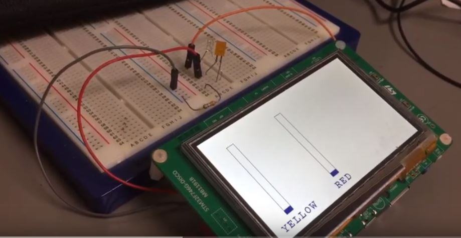
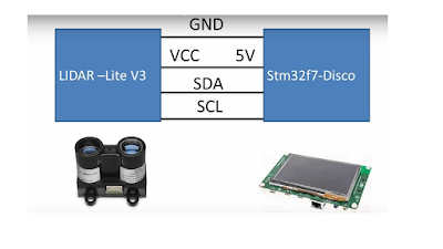
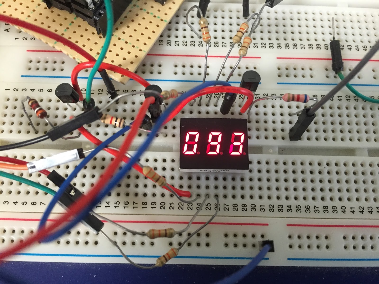
Connection
5V—————————————–5V
Gnd—————————————Gnd
Phase A———————————PH_6
Phase B———————————PI_3
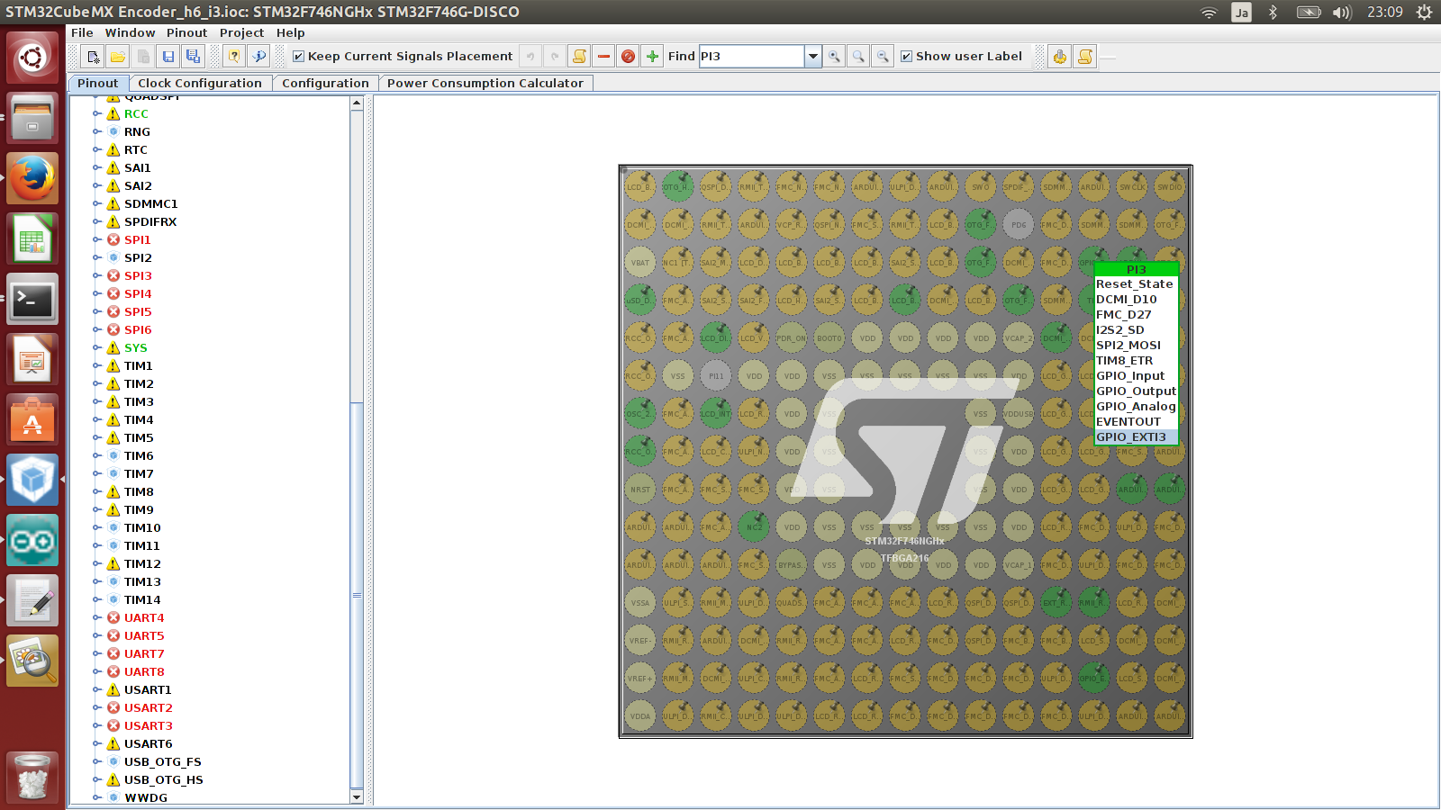
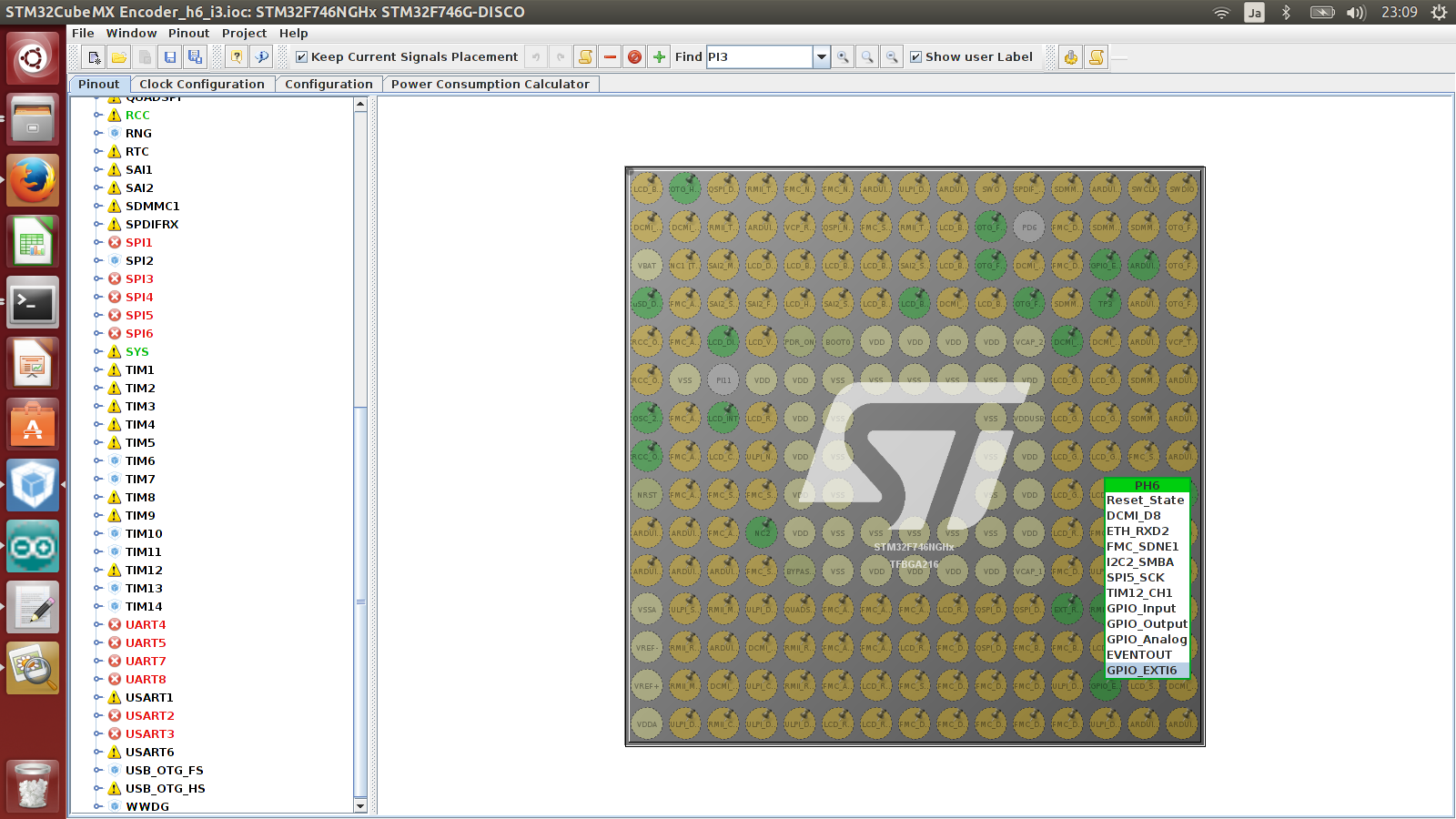
1.Pin out setting
Up system clock to 216 MHz
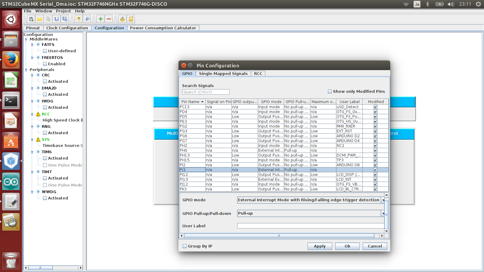
PH_6->EXTI6
PI_3->EXTI3

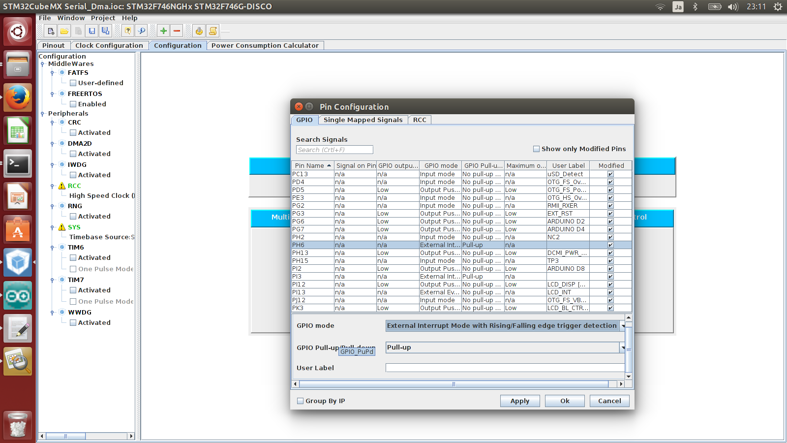
2. GPIO configuration
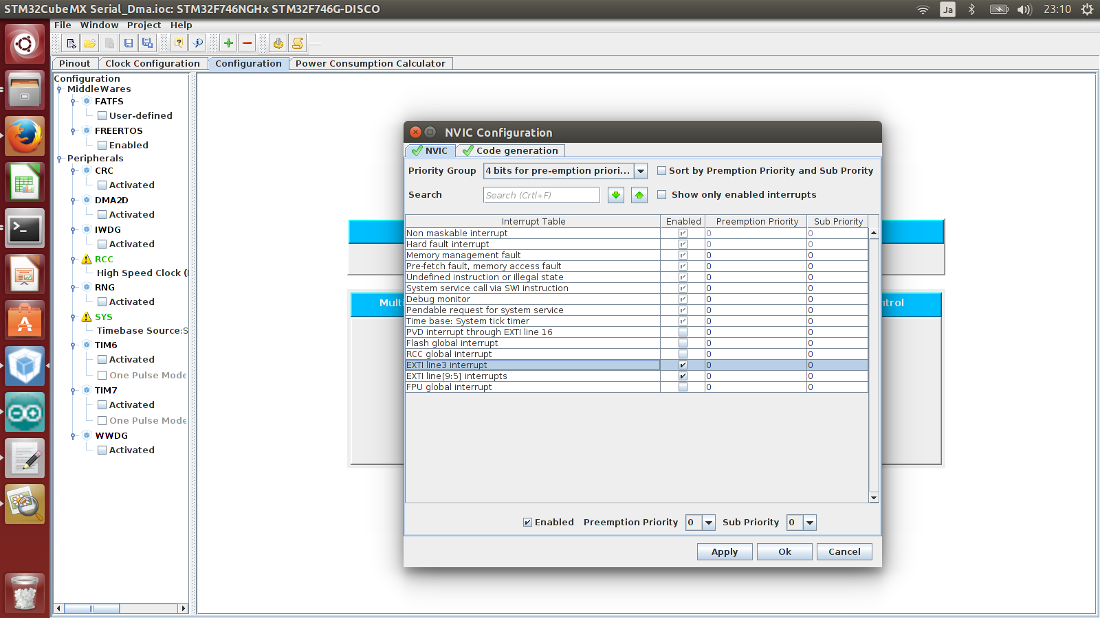
3. NVIC configuration
4. Source generation and edition
#include “stm32f7xx_hal.h”
#include “stm32f7xx_hal_uart.h”
#include “stm32f7xx_hal_sdram.h”
#include “stm32f7xx_hal_ltdc.h”
#include “stm32746g_discovery.h”
#include “stm32746g_discovery_lcd.h”
#include “stm32746g_discovery_sdram.h”
#include “stm32f7xx_ll_fmc.h”
extern uint8_t a,b,ab,c;
extern uint8_t pre_ab;
extern uint16_t count_;
——————————————————————————————-
int main(void)
{
HAL_Init();
SystemClock_Config();
MX_GPIO_Init();
BSP_LCD_Init();
BSP_LCD_LayerDefaultInit(0, LCD_FB_START_ADDRESS);
BSP_LCD_LayerDefaultInit(1, LCD_FB_START_ADDRESS+(BSP_LCD_GetXSize()*BSP_LCD_GetYSize()*4));
BSP_LCD_DisplayOn();
BSP_LCD_SelectLayer(0);
BSP_LCD_Clear(LCD_COLOR_BLACK);
BSP_LCD_SelectLayer(1);
BSP_LCD_Clear(LCD_COLOR_BLACK);
BSP_LCD_SetFont(&LCD_DEFAULT_FONT);
BSP_LCD_SetBackColor(LCD_COLOR_WHITE);
BSP_LCD_SetTextColor(LCD_COLOR_DARKBLUE);
char buffer[10];
while (1)
{
BSP_LCD_Clear(LCD_COLOR_WHITE);
sprintf(buffer,”count=%d”,count_);
BSP_LCD_DisplayStringAt(0, LINE(4), (uint8_t *)buffer, CENTER_MODE);
HAL_Delay(100);
}
}
In Src/stm32f7xx_it.c add
———————————————————————————————————————-
uint8_t a,b,ab,c;
uint8_t pre_ab=0;
uint16_t count_=0;
———————————————————————————————-
void EXTI3_IRQHandler(void)
{
HAL_GPIO_EXTI_IRQHandler(GPIO_PIN_3);
a =HAL_GPIO_ReadPin(GPIOI,GPIO_PIN_3);
ab=b<<1|a;
c=ab<<2|pre_ab;
pre_ab=ab;
if((c%5)!=0){
c=c|0x06;
if(c%3==0){
count_+=1;
}
else if(c%3!=0){
count_-=1;
}
}
}
void EXTI9_5_IRQHandler(void)
{
HAL_GPIO_EXTI_IRQHandler(GPIO_PIN_6);
b = HAL_GPIO_ReadPin(GPIOH,GPIO_PIN_6);
}
Video Stm32cubemx + Stm32f7-Disco Get data encoder (With GPIO interrupt)
Each STM32F4 device has 23 external interrupt or event sources. They are split into 2 sections. First interrupt section is for external pins (P0 to P15) on each port, and other section is for other events, like RTC interrupt, Ethernet interrupt, USB interrupt and so on.
October 1, 2014: Added external interrupts library.
GPIO as Interrupt
Interrupt lines
I will show now how to configure GPIO pin to be an interrupt and how to handle it in your code with CMSIS function.
In section one (GPIOs) we have 16 interrupt lines. They are line0 to line15 and they also represent pin number. This means, PA0 is connected to Line0 and PA13 is connected to Line13.
You have to know that PB0 is also connected to Line0 and PC0 also and so on. This is for all pins on board, All Px0 (where x is GPIO name) pins are connected to Line0 and let’s say all Px3 are connected to Line3 on the Interrupt channel.
All pins with same number are connected to line with same number. They are multiplexed to one line.
IMPORTANT: You can not use two pins on one line simultaneously:
- PA0 and PB0 and PC0 and so on, are connected to Line0, so you can use only one pin at one time to handle interrupt from there.
- PA0 and PA5 are connected to different lines, they can be used at the same time.
Each line can trigger an interrupt on rising, falling or rising_falling enge on signal.
Interrupt handlers
OK, now you have selected your pin you want to use. But you have to handle interrupt somehow. This process is described below.
STM32F4 has 7 interrupt handlers for GPIO pins. They are in table below:
| Irq | Handler | Description |
|---|---|---|
| EXTI0_IRQn | EXTI0_IRQHandler | Handler for pins connected to line 0 |
| EXTI1_IRQn | EXTI1_IRQHandler | Handler for pins connected to line 1 |
| EXTI2_IRQn | EXTI2_IRQHandler | Handler for pins connected to line 2 |
| EXTI3_IRQn | EXTI3_IRQHandler | Handler for pins connected to line 3 |
| EXTI4_IRQn | EXTI4_IRQHandler | Handler for pins connected to line 4 |
| EXTI9_5_IRQn | EXTI9_5_IRQHandler | Handler for pins connected to line 5 to 9 |
| EXTI15_10_IRQn | EXTI15_10_IRQHandler | Handler for pins connected to line 10 to 15 |
This table show you which IRQ you have to set for NVIC (first column) and function names to handle your interrupts (second column). You have probably also figured, that only lines 0 to 4 have own IRQ handler. Yes, lines 5-9 have the same interrupt handler and this is also for lines 10 to 15.
After you set settings for EXTI, you have to add them into NVIC. More about NVIC is described here.
Example
In this example, we will set pin PD0 and PB12 to be a GPIO interrupts. Code below should be well documented to understand how it works.
|
1
2
3
4
5
6
7
8
9
10
11
12
13
14
15
16
17
18
19
20
21
22
23
24
25
26
27
28
29
30
31
32
33
34
35
36
37
38
39
40
41
42
43
44
45
46
47
48
49
50
51
52
53
54
55
56
57
58
59
60
61
62
63
64
65
66
67
68
69
70
71
72
73
74
75
76
77
78
79
80
81
82
83
84
85
86
87
88
89
90
91
92
93
94
95
96
97
98
99
100
101
102
103
104
105
106
107
108
109
110
111
112
113
114
115
116
117
118
119
120
121
122
123
124
125
126
127
128
129
130
131
132
133
134
135
136
137
138
139
140
141
142
143
|
/**
* External interrupts example
*
* @author Tilen Majerle
* @email tilen@majerle.eu
* @website http://stm32f4-discovery.net
* @ide Keil uVision 5
*/
#include “stm32f4xx.h”
#include “stm32f4xx_exti.h”
#include “stm32f4xx_syscfg.h”
#include “misc.h”
/* Configure pins to be interrupts */
void Configure_PD0(void) {
/* Set variables used */
GPIO_InitTypeDef GPIO_InitStruct;
EXTI_InitTypeDef EXTI_InitStruct;
NVIC_InitTypeDef NVIC_InitStruct;
/* Enable clock for GPIOD */
RCC_AHB1PeriphClockCmd(RCC_AHB1Periph_GPIOD, ENABLE);
/* Enable clock for SYSCFG */
RCC_APB2PeriphClockCmd(RCC_APB2Periph_SYSCFG, ENABLE);
/* Set pin as input */
GPIO_InitStruct.GPIO_Mode = GPIO_Mode_IN;
GPIO_InitStruct.GPIO_OType = GPIO_OType_PP;
GPIO_InitStruct.GPIO_Pin = GPIO_Pin_0;
GPIO_InitStruct.GPIO_PuPd = GPIO_PuPd_UP;
GPIO_InitStruct.GPIO_Speed = GPIO_Speed_100MHz;
GPIO_Init(GPIOD, &GPIO_InitStruct);
/* Tell system that you will use PD0 for EXTI_Line0 */
SYSCFG_EXTILineConfig(EXTI_PortSourceGPIOD, EXTI_PinSource0);
/* PD0 is connected to EXTI_Line0 */
EXTI_InitStruct.EXTI_Line = EXTI_Line0;
/* Enable interrupt */
EXTI_InitStruct.EXTI_LineCmd = ENABLE;
/* Interrupt mode */
EXTI_InitStruct.EXTI_Mode = EXTI_Mode_Interrupt;
/* Triggers on rising and falling edge */
EXTI_InitStruct.EXTI_Trigger = EXTI_Trigger_Rising_Falling;
/* Add to EXTI */
EXTI_Init(&EXTI_InitStruct);
/* Add IRQ vector to NVIC */
/* PD0 is connected to EXTI_Line0, which has EXTI0_IRQn vector */
NVIC_InitStruct.NVIC_IRQChannel = EXTI0_IRQn;
/* Set priority */
NVIC_InitStruct.NVIC_IRQChannelPreemptionPriority = 0x00;
/* Set sub priority */
NVIC_InitStruct.NVIC_IRQChannelSubPriority = 0x00;
/* Enable interrupt */
NVIC_InitStruct.NVIC_IRQChannelCmd = ENABLE;
/* Add to NVIC */
NVIC_Init(&NVIC_InitStruct);
}
void Configure_PB12(void) {
/* Set variables used */
GPIO_InitTypeDef GPIO_InitStruct;
EXTI_InitTypeDef EXTI_InitStruct;
NVIC_InitTypeDef NVIC_InitStruct;
/* Enable clock for GPIOB */
RCC_AHB1PeriphClockCmd(RCC_AHB1Periph_GPIOB, ENABLE);
/* Enable clock for SYSCFG */
RCC_APB2PeriphClockCmd(RCC_APB2Periph_SYSCFG, ENABLE);
/* Set pin as input */
GPIO_InitStruct.GPIO_Mode = GPIO_Mode_IN;
GPIO_InitStruct.GPIO_OType = GPIO_OType_PP;
GPIO_InitStruct.GPIO_Pin = GPIO_Pin_12;
GPIO_InitStruct.GPIO_PuPd = GPIO_PuPd_UP;
GPIO_InitStruct.GPIO_Speed = GPIO_Speed_100MHz;
GPIO_Init(GPIOB, &GPIO_InitStruct);
/* Tell system that you will use PB12 for EXTI_Line12 */
SYSCFG_EXTILineConfig(EXTI_PortSourceGPIOB, EXTI_PinSource12);
/* PB12 is connected to EXTI_Line12 */
EXTI_InitStruct.EXTI_Line = EXTI_Line12;
/* Enable interrupt */
EXTI_InitStruct.EXTI_LineCmd = ENABLE;
/* Interrupt mode */
EXTI_InitStruct.EXTI_Mode = EXTI_Mode_Interrupt;
/* Triggers on rising and falling edge */
EXTI_InitStruct.EXTI_Trigger = EXTI_Trigger_Rising_Falling;
/* Add to EXTI */
EXTI_Init(&EXTI_InitStruct);
/* Add IRQ vector to NVIC */
/* PB12 is connected to EXTI_Line12, which has EXTI15_10_IRQn vector */
NVIC_InitStruct.NVIC_IRQChannel = EXTI15_10_IRQn;
/* Set priority */
NVIC_InitStruct.NVIC_IRQChannelPreemptionPriority = 0x00;
/* Set sub priority */
NVIC_InitStruct.NVIC_IRQChannelSubPriority = 0x01;
/* Enable interrupt */
NVIC_InitStruct.NVIC_IRQChannelCmd = ENABLE;
/* Add to NVIC */
NVIC_Init(&NVIC_InitStruct);
}
/* Set interrupt handlers */
/* Handle PD0 interrupt */
void EXTI0_IRQHandler(void) {
/* Make sure that interrupt flag is set */
if (EXTI_GetITStatus(EXTI_Line0) != RESET) {
/* Do your stuff when PD0 is changed */
/* Clear interrupt flag */
EXTI_ClearITPendingBit(EXTI_Line0);
}
}
/* Handle PB12 interrupt */
void EXTI15_10_IRQHandler(void) {
/* Make sure that interrupt flag is set */
if (EXTI_GetITStatus(EXTI_Line12) != RESET) {
/* Do your stuff when PB12 is changed */
/* Clear interrupt flag */
EXTI_ClearITPendingBit(EXTI_Line12);
}
}
int main(void) {
/* System init */
SystemInit();
/* Configure PD0 as interrupt */
Configure_PD0();
/* Configure PB12 as interrupt */
Configure_PB12();
while (1) {
}
}
|
Make a feedback if this tutorial a little bit helps to understand external interrupts on STM32F4 device.