Table of Contents
The assembly is very simple, it is composed of:
A)a fixed body (the vertical shaft to which the first gear is fixed , they do not rotate and does not move)
B) the moving bodies: the horizontal shaft (motor), which being free to turn both on its axis and on the vertical one, will turn the box into which it is inserted (with tho radial spherical bearings ).
I should also understand how to set the ratio so that 90 degrees of rotation on the vertical axis correspond to 90 degrees of rotation of the horizontal shaft axis, in practice 1: 1.
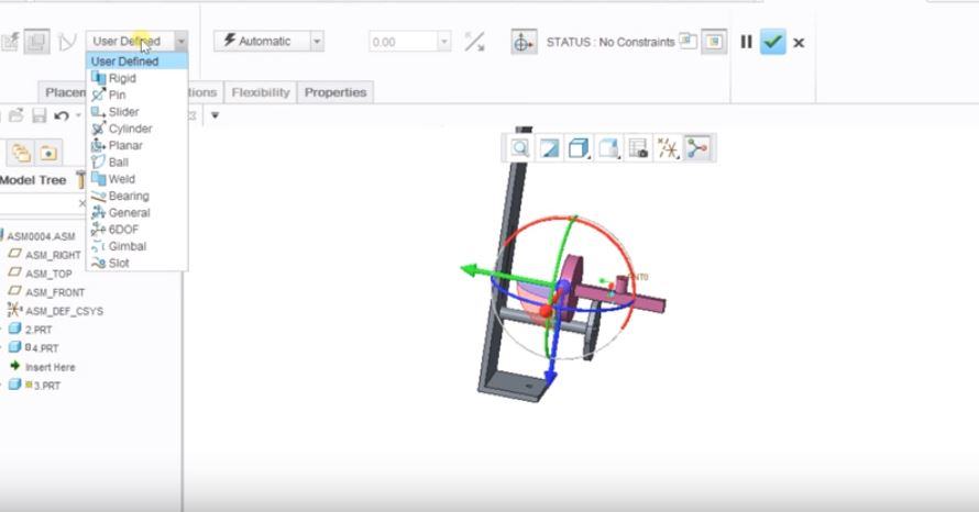
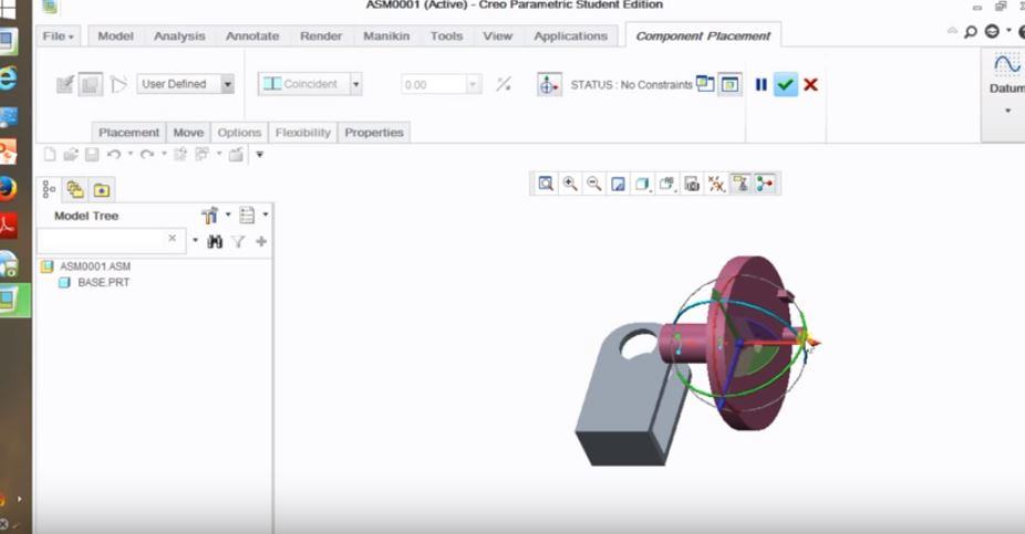
Reading the guide I understand that to use the mechanisms in Creo Parametric you must use the constraints defined by the user instead of the automatic contraints , my problem is to understand where to put them.
For example, I would have left like this:
1) the vertical shaft placed as default / fixed
2) Its ring is fixed on the shaft with automatic constraint , without any degree of freedom.
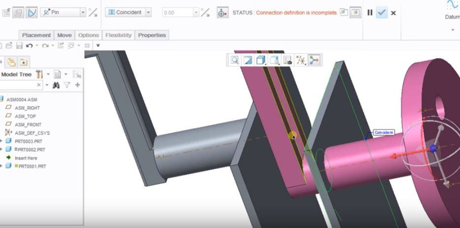
3) horizontal shaft with pin constraint , to allow rotation on its axis, inside the box
4) pin contrant also for the box, free to rotate around the vertical axis (or should I to constraint it to the horizontal shaft by matching the axes of the box holes with the orizontal shaft axis, plus the corresponding horizontal planes?)
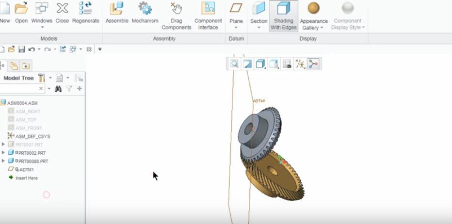
Then I would go into applications> mechanism and define a bevel gear (translate conical pair gear) . However, here it allows me to select only axes that can rotate, so that of the horizontal shaft and that of the box (if constrained with pin)


